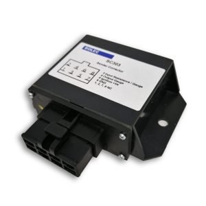
Fuel Sender & Gauge Corrector Module
The Bolec SC303 enables a resistive sender and gauge that were not originally designed to work together to provide a usable reading after calibration. Compatibility depends on the actual sender and gauge.

For resistive sender systems only. Check sender and gauge compatibility before ordering →
Before you buy — check compatibility
Bi-metal / thermal gauges are generally NOT compatible. Some exceptions may apply. Contact Bolec with your actual gauge and sender details before purchasing or installing the SC303.
- Resistive senders only. Not suitable for capacitive senders, including those used on XD and XE Falcons.
- 12/24 VDC, negative-ground systems only. The module requires power to operate.
- Calibration is required. Empty and Full are the basic starting points; intermediate points may be needed for a better match.
- Both the sender and gauge must work correctly. The SC303 cannot repair a faulty gauge or a worn, intermittent or open-circuit sender.
- Check non-standard applications first. Temperature, pressure, LPG and additional-gauge arrangements require confirmation of the actual components.
Ask Bolec about compatibility — include gauge and sender model numbers, supply voltage and known Empty / Full resistance values.
Different Senders and Gauges Use Different Resistance Characteristics
A sender from one manufacturer may not correctly operate a gauge from another manufacturer. The gauge may read backwards, show Empty when the tank is Full or become inaccurate through the middle of its range.
Convert the Sender Signal Before It Reaches the Gauge
The SC303 is installed between the sender and gauge. It reads the sender input and produces a corrected output that emulates the signal originally expected by the gauge.
SC303 Sender Corrector Overview
Watch the SC303 product overview to learn more about its intended applications and operation.
Typical Applications
How the SC303 Operates
Read the Sender Input
The SC303 monitors the voltage produced by the resistive sender circuit.
Apply the Conversion Curve
The module converts the input using the programmed reference points.
Drive the Gauge
The corrected output emulates the signal expected by the gauge.
In the most basic setup, Empty and Full positions are programmed. The SC303 then interpolates the output between these points.
Intermediate points such as 1/4, 1/2 and 3/4 can be added sequentially. Up to eight reference points can be stored to improve accuracy through the full gauge range.
Understanding the sender and gauge
The sender changes resistance as the fuel level changes. In a conventional resistive gauge circuit, the gauge and sender form a voltage divider. The resulting voltage depends on the components used, so sender resistance values and the direction of change must be checked for your actual system.


How the SC303 corrects the signal
The SC303 reads the sender input voltage and produces a corrected output voltage that emulates the signal expected by a compatible gauge. It uses your programmed reference points to match the sender to the gauge; it does not automatically identify their resistance ranges.

Pull-up ON is essential for the replacement sender/gauge arrangement shown. Without it, the sender input remains at zero and correction will not work as intended.
Key Features
Adjustable Fuel-Slosh Delay
Fuel moving inside the tank while cornering, braking or travelling over uneven surfaces can cause the gauge needle to move rapidly. The adjustable slosh-delay function controls the rate of output change to provide a steadier gauge reading.
Wiring Connections

| Wire Colour | Function |
|---|---|
| Red | Ignition-switched positive supply |
| Black | Ground / negative |
| White | Signal input from the resistive sender or existing sender/gauge circuit |
| Blue | Corrected signal output to the gauge |
Pull-up ON: use when matching a replacement sender to an original gauge, or a replacement gauge to an original sender.
Pull-up OFF: use for a compatible gauge-mirroring arrangement that reads an existing sender/gauge circuit. Confirm the arrangement with Bolec; do not assume that two gauges can simply be connected in parallel.
Calibration Overview
Confirm that the sender and gauge operate correctly before calibration.
Select the correct pull-up setting for the intended application.
Install the module between the sender and gauge.
Enter programming, set the sender to Empty and adjust the trim pot until the gauge reads Empty. Press SET to record the point.
Add known 1/4, 1/2 and 3/4 points if needed. Adjust the trim pot and press SET at each point; up to eight points total.
Adjust until the gauge reads Full and press SET. Then press PROG to exit and save the calibration to permanent memory.
Use the full instruction manual for the button sequence. Reference points must follow the fuel-level sequence from Empty to Full, or the reverse. Two endpoints give a straight-line conversion and may leave the middle of the range inaccurate. For an irregular tank, use reference points that correspond to known fuel levels.
- Check sender resistance with the sender isolated from the powered circuit. Do not measure resistance in a powered calibration circuit.
- Turn the trim pot at each new point. If adjustment is not triggered within approximately 25 seconds, programming times out without keeping the changes.
- Allow the gauge to settle before recording each point.
- Substitute resistors are an alternative when the sender cannot be removed, but actual sender values may differ from published specifications. Further adjustment may be needed.
Operating and Diagnostic Display
Normal Operation
The centre display segment flashes approximately once per second during normal operation within the calibrated range.
Out of Range
The sender input is beyond the programmed range. The SC303 extrapolates using the nearest end gradient; it does not simply hold the endpoint reading.
Sender Error
Indicates that the sender input is detached or driven to 0 V or supply voltage. Check the sender circuit and connections.
The out-of-range indicator is described as “o” and “0” in the original instructions; both refer to input outside the programmed range.
Specifications
| Model | SC303 |
|---|---|
| Supply voltage | 12/24VDC |
| Electrical system | Negative ground |
| Typical current draw | 30mA quiescent |
| Sender type | Resistive only |
| Input | Resistive sender systems only; 0–12 VDC or 0–24 VDC. |
| Input pull-up resistor | 235Ω internal pull-up included |
| Output | For compatible resistive gauge systems; 0–12 VDC or 0–24 VDC. External pull-up resistor not required. |
| Calibration points | Up to 8 sequential reference points |
| Product dimensions | 65L × 85W × 31H mm |
| Mounting centres | 75 mm |
| Mounting clearance | 4.5 mm |
SC303 Instruction Manual
Read the complete installation, wiring, calibration, slosh-delay and diagnostic instructions before setup. This product description is a buying guide and calibration overview.
Opens securely in DocSend in a new browser tab.
Unsure Whether the SC303 Will Suit Your Application?
Send Bolec Electronics the gauge type, sender type, supply voltage and known Empty and Full resistance values so compatibility can be reviewed before ordering.