Australian Made Since 1978 Quality Reliability Local Support
Australian Made Since 1978

Type a product name or part number, then tap Search.

Bolec SS301 Speed/Rev Switch 12/24VDC Multi Range +Mag Pickup kit
$250.00
6 in stock
SS301 Multi-Range Speed / Rev Switch – 12/24VDC+ Mag pickup M16, 1.5mm thread
The SS301 monitors a suitable frequency signal from a magnetic pickup,
ignition coil, ECU or sensor and provides a ground-switched output when
the selected frequency is reached. A key application is speed-dependent
bus door interlock and door lock-out control, alongside automotive,
agricultural and industrial alarm, shutdown and speed-control circuits.
- Frequency range: 10 Hz to 12,000 Hz
- Sine or square-wave input: 1.5–50 VAC, up to 12 kHz
- 12VDC or 24VDC selection by DIP switch
- Bus door interlock / door lock-out applications
- Coarse and fine set-point adjustment with adjustable hysteresis
- Stated rating: 3 A at 12VDC or 1.5 A at 24VDC
- Compact dimensions: approximately 58 × 42 × 29 mm
Bus door application:
In a compatible, properly engineered system, the SS301 can inhibit bus door opening
while the vehicle is moving or command the door-control circuit to its safe state
above the selected speed threshold.
Safety: The SS301 must be used as part of a fail-safe door-control
system. Confirm signal compatibility, relay logic and behaviour during signal or power loss.
Wiring diagram:
A labelled SS301 pin layout and connection guide is included in the technical information below.
Product document:
The available SS301 datasheet contains the product specifications and operating limits.
Product resources
BOLEC Product catalogue / Speed switch overview

Frequency-operated speed control module
SS301 Mag Pickup kit (M16 1.5mm thread)
Multi-Range Speed / Rev Switch — 12/24VDC
- 10–12,000 Hz range
- 12V / 24V DC selection
- Sine or square-wave input
- Bus door interlock applications
- 58 × 42 × 29 mm
- Mag pickup M16, 1.5mm thread
bolec.com.au | sales@bolec.com.au | 0480 312 400
SS301 technical overview
Speed-activated control for bus door interlocks, alarms and shutdown
The SS301 monitors a frequency signal from a suitable pickup, ignition, ECU or sensor source and provides a ground-switched output when the preset frequency is reached. In compatible bus applications, this output can form part of a door safety interlock or door lock-out circuit.
Wiring diagram included below. The connection guide identifies the SS301 controls, connector terminals, power supply, frequency-signal input and ground-switched output circuit.- 10 Hz to 12 kHz
- 12VDC or 24VDC
- Adjustable set point and hysteresis
- Bus door interlock / door lock-out
- Onboard setup LED
A4 catalogue layout — print or choose “Save as PDF”. Print this page
Product overview
Frequency sensing across a wide operating range
SS301 is designed for suitable bus, automotive, agricultural and industrial systems that require an output at a predetermined frequency or speed. A common vehicle application is speed-dependent bus door interlock control.Wide adjustment range
The stated operating range is 10 Hz to 12,000 Hz, with coarse and fine adjustment for set-point calibration.Stable switching
Adjustable hysteresis helps prevent output chatter around the selected switching frequency. Product video
See the SS301 speed switch
Watch the existing SS301 product video below.Product video
Watch online: youtube.com/watch?v=aWp2hfU6ZNY Application examples
Typical SS301 uses
Use depends on the available signal, switching point, connected load and the overall safety design of the machine.Bus door safety interlock
Use the vehicle-speed signal to provide an interlock output once the selected road-speed threshold is reached. In a properly designed system, this can inhibit door opening while the bus is moving or command the door-control circuit to its safe state.Bus and heavy-vehicle function lock-out
Enable or disable a compatible auxiliary function according to vehicle speed, including door lock-out, warning or other speed-dependent control logic.Engine overspeed protection
Use a suitable engine-speed signal to initiate an alarm or shutdown circuit at a selected frequency.Speed-based alarms
Operate a lamp, buzzer or compatible relay interface once the preset speed threshold is reached.RPM limiting and protection circuits
Integrate the frequency-operated output into a suitable engine or equipment protection circuit.Agricultural and industrial machinery
Provide speed-dependent relay control where the available signal and load are compatible with the module.Bus door safety note:The SS301 should be integrated into a properly engineered, fail-safe door-control
system and should not be treated as the only safety device. Confirm the vehicle-speed
signal, switching threshold, output interface, relay logic and safe behaviour for
signal or power loss before installation.
Product data
Specifications
The values below are taken from the existing SS301 product information supplied for this page.| Supply voltage | 12 VDC or 24 VDC, selected by DIP switch |
|---|---|
| Ground system | Negative ground |
| Input signal | Sine or square wave, 1.5–50 VAC, up to 12 kHz |
| Frequency range | 10–12,000 Hz |
| Output action | Ground-switched output once the preset frequency is reached |
| Stated rating at 12 VDC | 3 A |
| Stated rating at 24 VDC | 1.5 A |
| Set-point adjustment | Coarse and fine adjustment |
| Hysteresis | Fully adjustable |
| Setup indication | Onboard LED indicator |
| Dimensions | Approximately 58 × 42 × 29 mm |
Adjustment and testing
Set the voltage, switching point and hysteresis
Use the controlled product document for the exact switch positions and calibration sequence.1. Select the supply voltage
Set the module for the correct 12 VDC or 24 VDC system before applying power.2. Confirm the signal
Check that the signal type, amplitude and maximum frequency are within the stated input range.3. Adjust the switching point
Use the coarse and fine controls to establish the required frequency threshold.4. Set hysteresis and verify
Adjust hysteresis for stable switching, then confirm operation using the onboard LED and the complete machine circuit.Do not calibrate from assumptions Confirm the actual signal frequency at the required machine or engine speed before relying on the output for protection.
Connection guide
SS301 pin layout and wiring diagram
Use this diagram to identify the adjustment controls and theOUT, GND−, SIGNAL and IGN+ connections.Wiring diagram and explanation
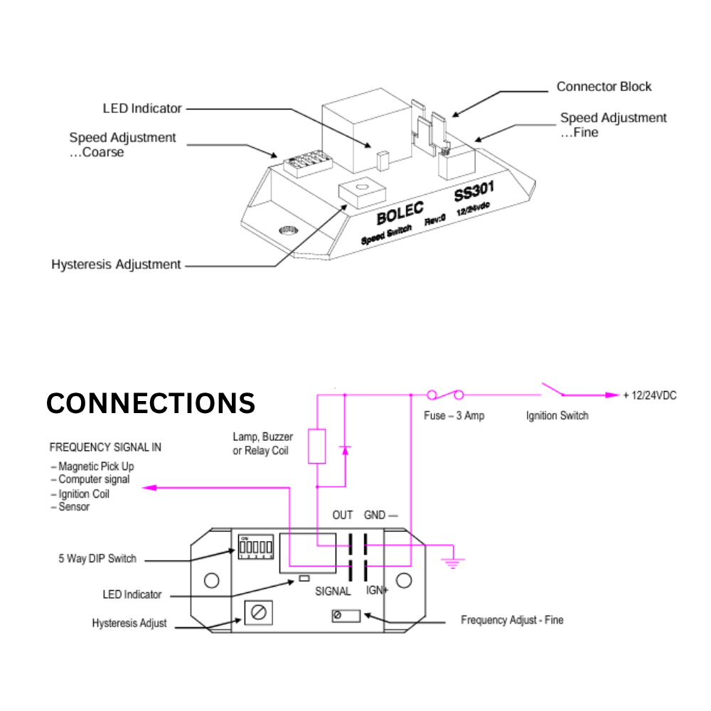
Power and signal
- IGN+: connect through the illustrated 3 A fuse and ignition switch to +12/24 VDC.
- GND−: connect to the negative-ground system.
- SIGNAL: connect the compatible frequency input from a magnetic pickup, computer/ECU signal, ignition coil or sensor.
Ground-switched output
- OUT: provides the ground-switched output for a compatible lamp, buzzer or relay coil.
- Fit a reverse-EMF suppression diode across relay or solenoid coils, as shown in the diagram.
- Confirm the connected load is within the stated SS301 output rating.
Installation notes
Signal, load and fail-safe considerations
Installation suitability depends on the complete circuit, not only the SS301 module.Included with the module
- 1 × SS301 Speed Switch module
- 1 × 4-way male mating connector
- 4 × brass crimp terminals
Coil suppression
Fit reverse-EMF diodes across relay and solenoid coils where applicable to protect the control circuit from voltage spikes.Design the system to fail safe The SS301 is a universal module but may not suit every signal or control system. Confirm compatibility and design the overall protection circuit to fail safe wherever practical.
Product selection guide
Read the SS301 vs SS501 comparison Open the Bolec comparison article for product-selection guidance.
SS301 vs SS501 — which Bolec speed switch suits the application?
Use the comparison guide when deciding between the SS301 and SS501 products.
Frequently asked questions
SS301 FAQ
Quick answers about signal input, operating voltage, frequency range and output setup.Can the SS301 be used for a bus door interlock?
Yes. Bus door interlock and door lock-out are established SS301 applications.
The module can use a compatible vehicle-speed signal and provide a ground-switched
output at the selected threshold. The complete door-control circuit must be designed
and verified as a fail-safe system, including its behaviour if signal or power is lost.
What type of signal can the SS301 use?
The stated input is a sine or square-wave signal from a suitable source such as a magnetic pickup, ignition coil, ECU or sensor. The input level is stated as 1.5–50 VAC, up to 12 kHz.
Does the SS301 work on both 12V and 24V systems?
Yes. Select the correct 12 VDC or 24 VDC setting with the DIP switch before connecting the module.
What frequency range can be adjusted?
The stated range is 10 Hz to 12,000 Hz.
Why is hysteresis adjustment important?
Hysteresis separates the switch-on and switch-off points so the output is less likely to chatter when the input frequency is close to the set point.
Can the SS301 be used in every engine or machine?
No universal module is compatible with every system. Confirm supply, ground type, signal waveform and level, switching frequency, output load and the required fail-safe behaviour before installation.
Where can I get the exact setup instructions?
Download the available SS301 datasheet below. Contact Bolec for the latest controlled instruction information when detailed setup or application support is required.
Documents and help
Downloads and technical support
Use the current controlled document when configuring or installing the SS301. Download SS301 datasheet Open the available SS301 product specification PDF.
Request the instruction manual Email Bolec for the latest controlled SS301 setup information.
Application support Ask about signal compatibility, set point, load interfacing or product selection.
The controlled Bolec document and markings on the supplied product take precedence if any difference is found.
Application guides
Related guides
Read practical application notes and product guides from Bolec Electronics.

Speed switches – Comparison of Murphy, Hewitt and Bolec
Speed Switches – Comparison of Murphy, Hewitt and Bolec In this article, we will talk about speed switches, or rev switches. What is a… Read guide SS301 vs SS501: Which Bolec Speed Switch Should You Choose? Choosing the right Bolec Speed Switch is essential for reliable engine protection and performance… Read guide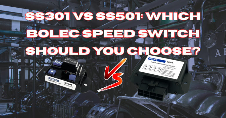
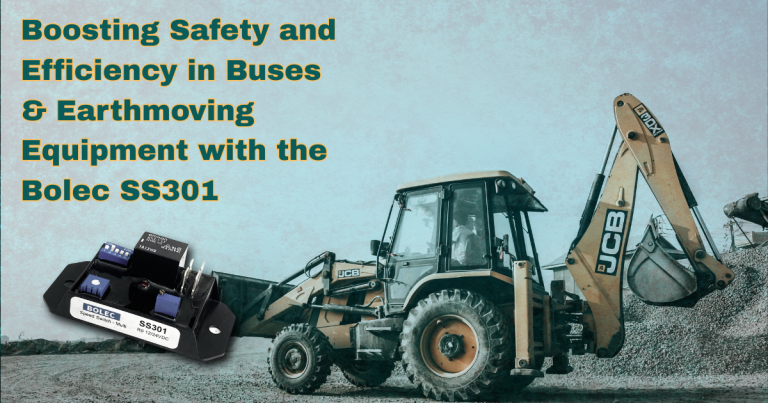
Boosting Safety and Efficiency in Buses & Earthmoving Equipment with the Bolec SS301 Speed Activated Switch
Boosting Safety and Efficiency in Buses & Earthmoving Equipment with the Bolec SS301 Speed Activated Switch When it comes to operating buses, trucks, and… Read guideRelated products
- Sale!

Workshop 10-Pack WL601P Low Water Level Probe (Push On)
Original price was: $240.00.$220.00Current price is: $220.00.Add to cart -

Bolec 12V Latching Relay Module – DPDT Momentary to Maintained ON/OFF
$80.00Add to cart -

Bolec ST -4 Electrical Turbo Timer 12/24V
$240.00Add to cart -

Bolec SS501 Dual Channel Speed/Rev Switch 12/24VDC
$275.00Add to cart -

Bolec VS203 Hi-Lo Voltage Switch 12/24VDC
$200.00Add to cart
