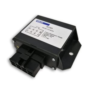
BOLEC VS203 · 12 V SYSTEMS · RELAY OUTPUT
Voltage Sensing Module
Monitor a DC supply and activate an external alarm or control circuit when the voltage rises above or falls below your selected limits.
The VS203 combines independent over-voltage and under-voltage adjustments with a changeover relay output and onboard power and relay indicators.

Specified input range: 9–16 VDC. Set the voltage thresholds to suit your application before use.
Before you buy — important limits
- For 12 V systems within a 9–16 VDC input range. Do not connect the module supply directly to a 24 V system. The 30 VDC marking on the relay is a contact rating, not the module’s supply rating.
- Relay output with N/O, N/C and COM contacts. Select the correct contact pair for the intended alarm or control action. The layout states a maximum contact rating of 5 A at 30 VDC.
- Voltage monitoring requires power. The alarm function energises the relay. Do not assume that a total loss of supply will produce the same contact state as a powered low-voltage alarm.
- Confirm load compatibility. Check the load’s operating current, starting current and switching requirements before connecting motors, solenoids or other demanding loads. Some input or output arrangements may not suit the module.
9–16 VDC
Specified module input-voltage range.
Two set points
Adjust over-voltage and under-voltage thresholds independently.
Changeover relay
N/O, N/C and COM output connections.
Recovery selection
Normal low-voltage recovery or approximately 2 V rising recovery.
Typical applications
The VS203 can provide an out-of-range voltage signal for suitable 12 V automotive, battery-supply and engine-control circuits. Use the relay contacts to interface with a compatible external warning or control circuit.
Choose the thresholds according to the equipment being monitored. The VS203 switches an output when voltage is outside the selected limits; it does not regulate the supply voltage or charge the battery.
How the VS203 operates
1. Monitor the DC input
Connect the monitored supply to the module’s positive and ground input terminals, following the layout below.
2. Compare the voltage
The module monitors the input against separate under-voltage and over-voltage set points.
3. Switch the relay
When the input goes above or below the set points, the relay energises and the red relay LED lights.
Understand the relay contacts
| Relay state | Contact connection |
|---|---|
| De-energised | COM connects to N/C; COM to N/O is open. |
| Energised | COM connects to N/O; COM to N/C is open. |
N/O and N/C describe the relay’s de-energised contact positions. They do not mean “normal voltage” and “fault voltage”. Low-voltage recovery mode also affects when the relay returns after a low-voltage alarm.
Terminal layout and wiring
Use the terminal labels and orientation in this drawing when connecting the module. The two adjustment pots are separately labelled for over-voltage and under-voltage.

| Terminal / indicator | Function |
|---|---|
| +12 VDC | Monitored positive supply input. Keep within 9–16 VDC. The drawing specifies a 500 mA supply fuse. |
| GND 0 V | Supply ground / negative reference. |
| COM | Relay common contact. The drawing shows a 5 A fuse on this connection. Fuse selection must also suit the wiring and connected load. |
| N/O | Normally open contact. Connects to COM when the relay energises. |
| N/C | Normally closed contact. Connects to COM when the relay is de-energised. |
| Green POWER LED | Supply-on indicator. |
| Red RELAY LED | Lights when the relay operates. |
5 A at 30 VDC is the relay contact limit
This rating does not permit a 30 V supply to the module. The module input remains limited to 9–16 VDC. Confirm suitability for the actual load before installation, especially where inrush current or inductive switching is involved.
Voltage thresholds and recovery settings
Independent over-voltage and under-voltage adjustments
Set the two potentiometers to the required high and low voltage limits. The published adjustment limits are over-voltage up to 16 VDC and under-voltage down to 9 VDC. Keep the under-voltage threshold below the over-voltage threshold and verify operation at both limits.
DIP switch functions
| Switch | Function shown in the instructions |
|---|---|
| DIP 1, 2 and 3 | Not in use. |
| DIP 4 OFF | Normal / instant low-voltage recovery mode. |
| DIP 4 ON | After a low-voltage alarm, the supply must rise by around 2 V to deactivate the alarm. |
Check the ON marking on the DIP switch body when selecting the position.
The recovery setting is a voltage change, not a delay in seconds
The supplied operation diagram identifies switches 1–3 as unused and switch 4 as the low-voltage recovery selection. Although the description refers to a “time delay”, no selectable delay times in seconds are specified. The approximately 2 V rising option changes the voltage required for recovery after a low-voltage alarm.
Choose a recovery setting that the monitored system can actually reach within the module’s specified input range. Confirm the required configuration with Bolec if a timed alarm delay is essential.
Setup and checking
1. Confirm the application
Check that the monitored supply is within the 9–16 VDC range and that the relay output is suitable for the connected circuit.
2. Wire the module
Connect supply, ground and the required relay contacts using the terminal layout and suitable circuit protection.
3. Set the voltage limits
Use the separate over-voltage and under-voltage pots to establish the required limits for the equipment.
4. Select recovery mode
Choose DIP 4 OFF for normal recovery or ON for approximately 2 V rising recovery after a low-voltage alarm.
5. Verify both alarms
With suitable test equipment, check relay and red LED operation at both thresholds while keeping the module input within its specified range.
6. Verify recovery
Check the return from a low-voltage alarm and confirm that the selected N/O or N/C circuit behaves as intended.
The supplied instructions do not specify a universal alarm voltage or a detailed potentiometer adjustment direction. Use settings appropriate to the battery, vehicle or equipment, and confirm the procedure with Bolec if required.
Technical specifications
| Item | Specification |
|---|---|
| Model | VS203 Voltage Switch — 12 V |
| Input voltage | 9–16 VDC |
| Supply current | Approximately 80 mA |
| Over-voltage adjustment | Up to 16 VDC |
| Under-voltage adjustment | Down to 9 VDC |
| Output | Changeover relay with N/O, N/C and COM terminals |
| Relay contact rating | 5 A at 30 VDC maximum, as marked on the supplied layout |
| Indicators | Supply-on LED and relay-operation LED |
| Low-voltage recovery | Normal / instant, or approximately 2 V rising recovery |
| DIP switch use | Switches 1–3 unused; switch 4 selects low-voltage recovery mode |
| Reverse-polarity protection | Included |
| Case material | Thermoplastic |
| Dimensions | 58 L × 42 W × 15 H mm |
Check your voltage-monitoring application
Send Bolec the normal supply range, required high and low alarm points, preferred recovery behaviour and details of the load or control circuit you want to switch.
Bolec Electronics · sales@bolec.com.au