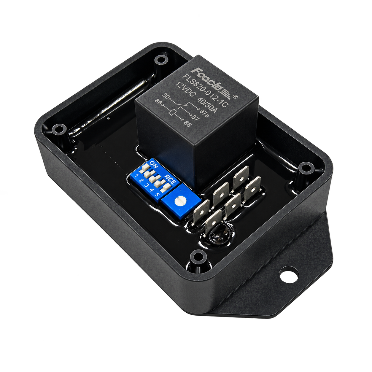
TM301HD-30A
Heavy Duty 12V Solenoid Timer Relay
An adjustable 12 VDC timer for compatible three-wire fuel solenoids. A timed pull-in pulse seats the plunger; the hold supply stays on while the run supply is on.
30 A Nominal
Seconds / Minutes
Pull & Hold
View instruction manualCheck load compatibility
12 VDC negative ground. Confirm solenoid inrush and DC inductive switching duty when selecting a load.
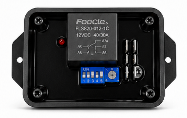
12 VDC • Adjustable timing
111 × 61.8 × 40 mm
Timed pull-in with a separate hold supply
When the switched supply is applied, the timer energises the pull coil for the selected period. The pull output then switches off, while the hold coil remains energised until the run supply is removed. This limits pull-coil energisation during extended cranking.
Use the shortest verified pulse that seats the plunger reliably, within the solenoid manufacturer’s permitted duty. The timer’s available range is not a recommended coil energisation duration.
Key Features
Nominal Relay Rating
30 A nominal product rating. Confirm permitted inrush and DC inductive switching duty for the actual load.
12V DC Model
12 VDC negative-ground operation. This HD version is not specified for 24 V systems.
Timing Ranges
Four DIP-selected ranges: 1–30 or 2–60 seconds, and 1–30 or 2–60 minutes.
Inhibit / Reset Input
A positive input resets the timer and holds it reset while applied. Leave INH+ unused in the illustrated solenoid circuit.
12V control applications
Suitable timing applications may include fuel solenoids, irrigation valves, actuators and other compatible 12 VDC loads. Check each load’s inrush, switching duty and required operating sequence. The three-wire circuit in the manual is specific to the pull-and-hold solenoid application.
Controls and terminal identification
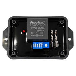
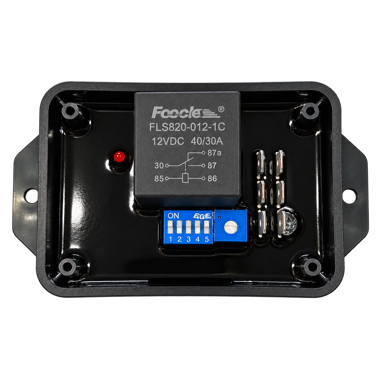
Use the same top-view orientation as the illustration: relay at the left and DIP switches at the bottom. The six module terminal names identify the external connections; relay case numbers describe the relay’s internal connections.
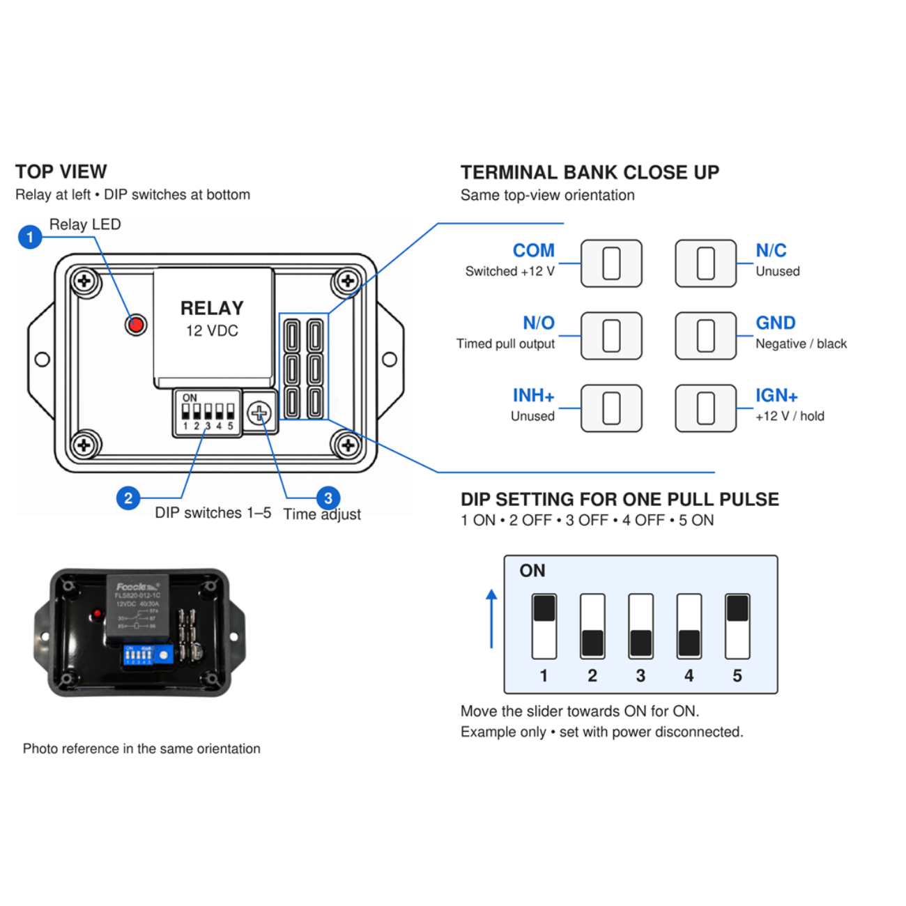
Relay left • DIP switches at bottom
1 Relay LED
The red LED lights when the relay is energised. It indicates relay state, rather than confirming solenoid seating.
2 DIP switches 1–5
Move a switch towards its printed ON side for ON. Disconnect power before changing the settings.
3 Time adjustment
Turn clockwise for a longer pulse and anticlockwise for a shorter pulse. Measure the output duration after adjustment.
Three-wire solenoid connections
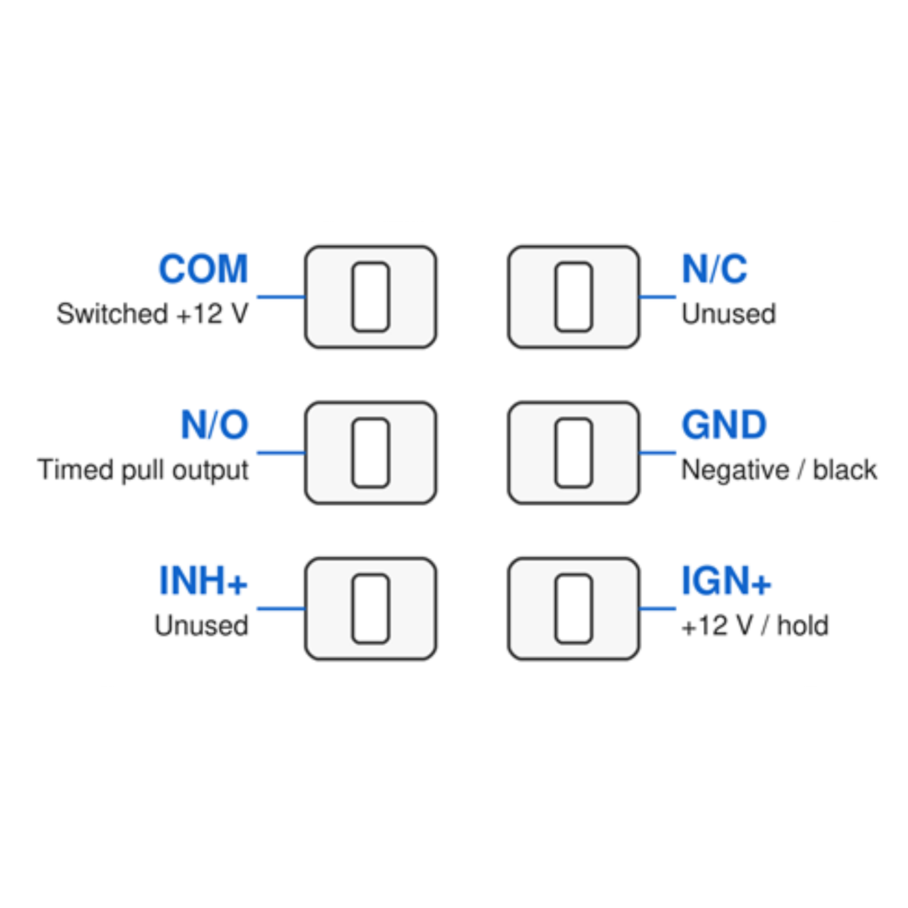
The switched, fused 12 V positive supply feeds COM, IGN+ and the solenoid hold coil. Fit the COM-to-IGN+ jumper. N/O supplies the timed pull coil, and GND connects to battery negative and the solenoid negative lead.
| Terminal and position | Connection for the solenoid circuit |
|---|---|
| COM • upper left | Switched, fused 12 V positive. Fit a jumper to IGN+. |
| N/C • upper right | Leave unconnected for this application. |
| N/O • middle left | Timed pull-coil output. Typically white (yellow) on the BT reference wiring. |
| GND • middle right | Battery negative / common ground and the solenoid black lead. |
| INH+ • lower left | Leave unconnected for this application. |
| IGN+ • lower right | Same switched 12 V positive as COM. The hold coil connects to this switched supply, typically brown (red) on the BT reference wiring. |
Confirm the actual solenoid leads. Lead colours vary between models. Use the labels or supplier data for the installed solenoid.
Size the complete power circuit for the load. Select the fuse, cable, terminals and power switch for pull-coil inrush plus hold current. A low-current ignition switch should control a suitably rated power relay. For loads beyond the timer’s confirmed switching capability, use a suitable external relay or contactor.
Check suppression and release. Fit suppression suitable for the solenoid and switching duty. In the manual’s circuit, D1 has its cathode at switched positive and suppresses the shared supply; it does not directly suppress the N/O pull-coil output. Confirm pull-coil suppression with the solenoid supplier.
For the complete functional circuit and commissioning procedure, view the instruction manual.
Selectable timer functions
Choose the operating function with the DIP switches. For the three-wire solenoid circuit, use an immediate single pulse.
Delay ON
Relay energises after the selected delay following power-up.
Instant ON, timed OFF
Relay energises immediately, then switches off after the selected time while the supply remains on.
Single operation
One timing operation after power-up. This is the mode used for the solenoid pull pulse.
Continuous cycling
Repeated ON/OFF timing operations. Leave this mode OFF for the three-wire solenoid circuit.
DIP switch settings and operation
The manual uses the five-switch TM301 configuration shown in the controls illustration. Verify that the supplied HD unit matches before installation. Disconnect power before changing DIP switches.
| DIP | OFF | ON |
|---|---|---|
| 1 | Delay ON after power-up | Instant ON, timed OFF |
| 2 | Single timing operation | Continuous ON/OFF cycling |
| 3 | Seconds | Minutes |
| 4 | 1–30 range | 2–60 range |
| 5 | Do not use on this 12 V HD unit | 12 V setting |
Single pull pulse for the solenoid circuit
1 ON • 2 OFF • 3 OFF • 4 OFF • 5 ON
This selects an immediate single pulse in the 1–30 second range. Adjust the pulse to the shortest measured time that seats the solenoid reliably, within its permitted energisation duty. Use a suitable timer configuration if the required duration is outside the available range.
- Supply ON: pull and hold coils energise; the solenoid seats.
- Pulse ends: N/O switches off; the hold coil keeps the solenoid seated.
- Supply OFF: both coils de-energise; the solenoid returns to the engine-stop position.
Measure the N/O pulse under the intended supply conditions. Removing and reapplying the switched supply starts a new pull-in pulse. Leave INH+ unused for this circuit.
Technical specifications
| Item | Specification |
|---|---|
| Part number | TM301HD-30A |
| Product type | Heavy Duty 12V Solenoid Timer Relay |
| Operating voltage | 12 VDC, negative ground. This HD version is not specified for 24 V operation. |
| Relay capacity | 30 A nominal product rating. Confirm permitted inrush and DC inductive switching duty for the actual load. |
| Timing ranges | 1–30 sec / 2–60 sec / 1–30 min / 2–60 min |
| Timer functions | Delay ON; instant ON, timed OFF; single operation; continuous cycling |
| Relay connections | COM, N/O and N/C |
| Control connections | IGN+ supply, GND negative and INH+ positive inhibit / reset |
| Indication | Red LED lights when the relay is energised |
| Dimensions | 111 × 61.8 × 40 mm, published HD enclosure dimensions |
| Mounting hole centres | 98 mm centre-to-centre |
| Mounting hole diameter | Two Ø5 mm holes |
Confirm timing accuracy, enclosure protection and environmental limits with Bolec for the intended installation.
Mounting dimensions
Mount securely in a protected location, clear of water, excessive heat and moving parts. Insulate terminals from metalwork. The solenoid linkage must move freely and let the plunger seat at its internal stop. Check the engine-stop position with power removed.
Installation and commissioning
Verify operation on the installed solenoid before putting the equipment into service.
- Isolate the battery. Confirm both timer and solenoid are suitable for 12 VDC, then check terminal names and solenoid lead functions.
- Wire the circuit and fit the selected fuse close to the supply. Check polarity, common ground, terminal retention and suppression polarity.
- Set single-pulse mode and a pulse within the solenoid’s permitted duty. Apply the switched supply and check that the plunger seats fully.
- Measure the N/O pulse. After it ends, confirm that the solenoid stays seated on the hold coil alone.
- Remove the supply and check the intended engine-stop function. Repeat under starting conditions to verify operation despite cranking voltage drop. Record final pulse time, load current and fuse selection.
Stop and isolate power if the plunger does not seat, the pull coil exceeds its permitted energisation duty, wiring heats up or shutdown does not operate correctly. Correct the cause before further testing.
Instruction manual and application support
View the full wiring circuit, switch settings, mounting guidance and fault checks. For application advice, send Bolec your supply voltage, solenoid model, pull and hold currents, and required pulse time.