SS301 Bus Door Switch – Speed-Activated Door Lock-Out, 12/24VDC
The SS301 monitors a compatible vehicle-speed or RPM frequency signal and provides a ground-switched output when the adjustable threshold is reached. It is intended for integration into bus door interlocks, heavy-equipment travel locks and other speed-dependent auxiliary control systems.
Bus door interlock and door lock-out applications
Earthmoving hydraulic or auxiliary-function travel lock-out
Selectable 10 Hz to 12,000 Hz frequency range
Sine or square-wave input: 1.5–50 VAC
12VDC or 24VDC negative-ground systems
Coarse and fine switching-point adjustment
Fully adjustable hysteresis to reduce output chatter
Ground-switched output: 3 A at 12VDC or 1.5 A at 24VDC resistive maximum
Approximate dimensions: 58 × 42 × 29 mm
Important bus door safety note: The SS301 must be integrated into a properly engineered and tested fail-safe door-control system. It must not be used as the only bus door safety device.
Product document: The available SS301 datasheet contains the product specifications and operating limits.
BOLECProduct catalogue / Bus door interlock switch
Speed-activated vehicle safety and lock-out control
SS301 Bus Door Switch
Bolec Heavy-Low Speed Switch Door Lock Out — 12/24VDC
Bus door interlock applications
10–12,000 Hz selectable range
12V / 24V DC selection
Ground-switched output
Approx. 58 × 42 × 29 mm
bolec.com.au | sales@bolec.com.au | 0480 312 400
SS301 bus and heavy-vehicle application
Speed-activated door interlock and heavy-equipment function lock-out
The SS301 monitors a compatible vehicle-speed or RPM frequency signal and
provides a ground-switched output once the adjustable threshold is reached.
In a correctly designed vehicle control system, this output can be used for
bus door lock-out, hydraulic travel lock-out, warnings and other speed-dependent functions.
The existing product title also identifies this model as the Bolec Heavy-Low Speed Switch Door Lock Out. The supplied product
information describes a single adjustable switching threshold with coarse,
fine and hysteresis adjustment.
Bus door interlock / door lock-out
12VDC or 24VDC negative-ground systems
Sine or square-wave input
Adjustable set point and hysteresis
Onboard setup LED
A4 catalogue layout — print or choose “Save as PDF”.
Product overview
One adjustable speed threshold for vehicle interlocks and auxiliary control
This application-focused SS301 listing is intended for compatible buses,
trucks and earthmoving equipment that require a control output when a
selected speed or frequency is reached.
Bus door lock-out
Use a compatible vehicle-speed signal to inhibit door opening or command the door-control circuit to its designed safe state while the vehicle is moving.
Adjustable activation point
Coarse and fine controls allow the switching frequency to be calibrated for the specific vehicle signal and required operating point.
Chatter prevention
Fully adjustable hysteresis helps prevent rapid on/off switching when the input is close to the selected threshold.
Operating principle
Frequency input in, ground-switched control output out
The SS301 converts a compatible speed-related frequency signal into a usable control output at the selected threshold.
1. Monitor the vehicle or engine signal
Connect a compatible sine or square-wave signal from a magnetic pickup, ECU/computer output, ignition coil or dedicated sensor.
2. Set the required threshold
Select the appropriate DIP-switch range, then use the coarse and fine controls to establish the switching point.
3. Stabilise the transition
Adjust hysteresis so the output does not chatter as vehicle speed moves slightly above and below the threshold.
4. Interface the output
The ground-switched output can operate a compatible lamp, buzzer or relay interface within the stated electrical rating.
Application examples
Bus, truck and earthmoving applications
Final suitability depends on the available signal, switching point, connected load and the overall vehicle safety design.
Bus door interlock systems
Provide a speed-dependent interlock signal intended to prevent doors from opening while the bus is moving.
Earthmoving equipment travel locks
Disable compatible hydraulic or auxiliary functions during transport or travel when the selected speed threshold is reached.
Speed-activated warnings
Trigger a warning lamp, buzzer or relay interface above a selected speed or RPM-related frequency.
Automated lubrication control
Activate a compatible lubrication control input according to engine RPM or travel-speed conditions.
Machine access control
Enable or disable a compatible function according to the machine’s operating state or speed.
Other heavy-vehicle auxiliary systems
Provide speed-dependent control where the signal, load interface and safety logic are compatible with the SS301.
Product data
Technical specifications
The values below are taken from the existing SS301 Bus Door Switch product information.
Product / SKU
SS301 Bus Door Switch / SS301-1
Supply voltage
12 VDC or 24 VDC, selectable
Ground system
Negative ground
Input signal
Sine or square wave, 1.5–50 VAC
Frequency range
10–12,000 Hz, selectable via DIP switches
Output action
Ground-switched output once the preset frequency is reached
Maximum stated resistive output at 12 VDC
3 A
Maximum stated resistive output at 24 VDC
1.5 A
Set-point adjustment
Coarse and fine adjustment
Hysteresis
Fully adjustable
Setup indication
Onboard LED indicator
Dimensions
Approximately 58 × 42 × 29 mm
Adjustment and testing
Set the voltage, frequency range, switching point and hysteresis
Use the controlled product document for the exact DIP-switch positions and calibration sequence.
1. Confirm the vehicle system
Verify negative-ground operation and select the correct 12 VDC or 24 VDC setting before applying power.
2. Measure the signal
Confirm the waveform, amplitude and frequency at the required road speed or machine operating point.
3. Select the range and set point
Choose the appropriate DIP-switch range, then use the coarse and fine controls to establish the threshold.
4. Set hysteresis and prove the system
Adjust hysteresis for stable switching, then test the complete door, hydraulic or warning circuit across all required operating conditions.
Calibrate from the actual vehicle signal Do not rely on an assumed relationship between road speed, engine RPM and input frequency.
Connection guide
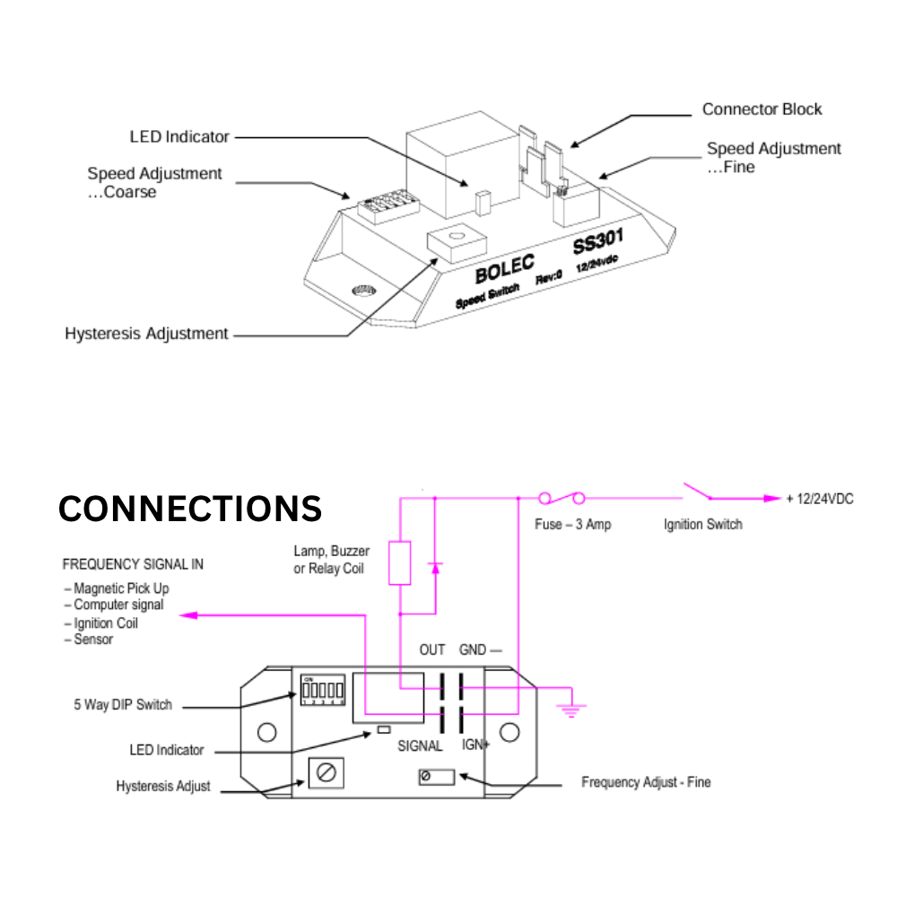
SS301 pin layout and wiring diagram
Use this diagram to identify the adjustment controls and the OUT, GND−, SIGNAL and IGN+ connections.
Wiring diagram and connection explanation
SS301 adjustment controls and typical negative-ground connection arrangement.
Select the image to open the full-size version.
Power and signal
IGN+: connect through the illustrated 3 A fuse and ignition switch to +12/24 VDC.
GND−: connect to the vehicle negative-ground system.
SIGNAL: connect the compatible frequency input from a magnetic pickup, computer/ECU signal, ignition coil or sensor.
Ground-switched output
OUT: provides the ground-switched output for a compatible lamp, buzzer or relay coil.
Fit a reverse-EMF suppression diode across relay or solenoid coils, as shown in the diagram.
Confirm the connected load remains within the stated SS301 resistive output rating.
Safety and installation
Integrate the SS301 into a verified fail-safe vehicle control system
The module provides a speed-dependent output; the installer remains responsible for the complete safety architecture and vehicle integration.
Define the safe state
Document the required door, hydraulic or auxiliary-system state for normal operation, overspeed, signal loss, power loss, open circuit and short circuit conditions.
Use a suitable output interface
Use an appropriately rated relay or interface where the controlled circuit exceeds the stated SS301 output rating or requires isolated contacts.
Suppress inductive loads
Fit a reverse-EMF diode across DC relay and solenoid coils to reduce voltage spikes and protect the switch output.
Validate the complete installation
Test the system at standstill, around the threshold, above the threshold and during simulated signal or supply faults before returning the vehicle to service.
Bus door safety warning:Do not use the SS301 as the only safety device. Bus door and heavy-equipment
lock-out circuits must be engineered, installed and tested so that a single
fault does not create an unsafe operating condition.
Product video
See the SS301 single-channel speed switch
Watch the existing Bolec SS301 product video below.
Quick answers about bus door interlocks, vehicle signals, setup and output interfacing.
How is the SS301 used in a bus door interlock?
The SS301 monitors a compatible speed-related frequency signal and changes
its ground-switched output when the selected threshold is reached. The
vehicle designer can use that output within a properly engineered circuit
to inhibit door opening or command the door-control system to its safe state.
Is the bus door switching speed adjustable?
Yes. Select the appropriate frequency range with the DIP switches, then use the coarse and fine controls to set the required threshold. Confirm the setting from the actual vehicle signal and road-speed test results.
What signal can the SS301 use?
The stated input is a sine or square-wave signal, 1.5–50 VAC, from a suitable source such as a magnetic pickup, ECU/computer signal, ignition coil or sensor.
Does it work on both 12V and 24V vehicles?
Yes. The supplied information states 12 VDC or 24 VDC negative-ground operation with voltage selection by DIP switch.
What frequency range is available?
The stated selectable range is 10 Hz to 12,000 Hz.
Can the output drive a bus door actuator or hydraulic solenoid directly?
Only when the connected load is compatible with the ground-switched output and remains within the stated resistive rating. Higher-current or inductive loads should be controlled through a suitable external relay or interface, with coil suppression fitted.
Can this module be the only bus door safety device?
No. The SS301 should form only one part of a properly engineered and validated fail-safe door-control system.
Where can I get the setup information?
Download the available SS301 datasheet below. Contact Bolec for the latest controlled instruction information and application support.
Documents and help
Downloads and technical support
Use the current controlled document when configuring or installing the SS301.
Founded in 1978, Bolec Electronics has developed a portfolio of over 80 products and a reputation that survive and thrive in some of Australia's harshest environments. Bolec Electronics is the OE supplier to some of the world's largest truck and engine manufactures.
Premium quality
Easy to install
lightweight
Designed and made in Australia
Session expired
Please log in again. The login page will open in a new tab. After logging in you can close it and return to this page.
READY TO ORDER? SS301 Bus door Switch – Bolec Heavy-Low Speed Switch Door Lock Out $210.00Original price was: $210.00.$200.00Current price is: $200.00.